Hobby Servo Motor Performance
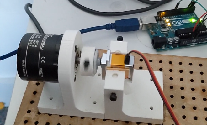
Table of Contents
A hobby servo is a small motor commonly found in remote control planes to position wing flaps and cars to control the steering.
Internally they are a brushed, sometimes brushless, dc motor connected to the output via a gearbox. A position sensor (potentiometer or encoder) is used to measure the output position and using feedback control, the output is moved to a desired position. The position demand is determined by the length of a pulse on one of the input pins.
This all in one construction with position control makes them quite popular for all sorts of projects, especially considering how cheap they are compared to the more `industrial’ options.
However one thing they lack compared to more proper alternatives is a datasheet. Typically the only performance information is the speed and torque. The torque I assume is stall torque, which is therefore easy enough to compare between motors (I assume it is peak rather than continuous), but the speed is more difficult.
Firstly, the speed is measured in seconds/60 degrees, so is in fact not speed but the inverse. And secondly I have no idea if that means top speed or time from 0 to 60. Probably the former as it makes the motor look more impressive.
In any case, the limited information makes comparing motors challenging, so when I needed a high performance servo motor, I thought I should try find out what the motors can actually do.
How to test the motors? #
The go-to methods for testing dynamic performance are a step response and a frequency response. The step response looks how the position changes when a step change in position demand is applied e.g from 0 to 60 degrees.
The frequency response looks at the relative magnitude and phase of the position response to a sine wave position demand at a range of different frequency. This is useful as it can give the bandwidth of the motor, and some idea of the usable frequency range.
Test setup #
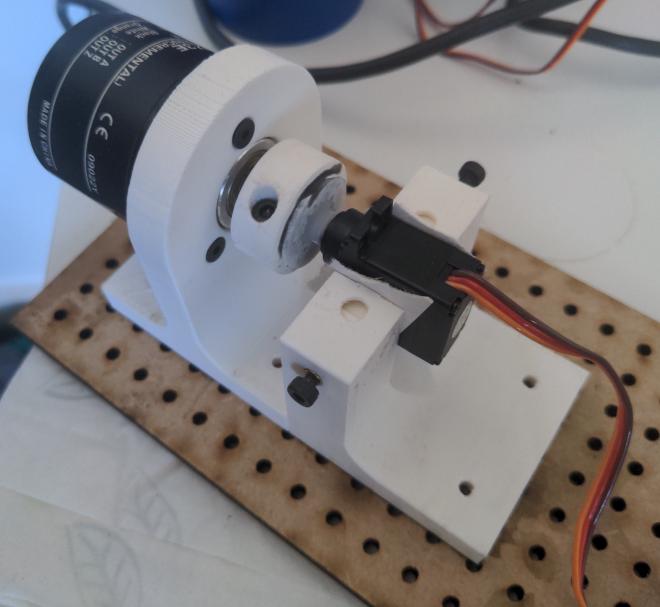
Whilst the motors contain a position sensor internally, it is not easily accessible, so one needs attaching to the output. I am using a relative encoder because its easy to get a velocity measurement and also because I had one to hand.
Next, something to tell the motor what to do and measure the encoder position. An Arduino UNO will do that job nicely.
With a bit of 3D printing, laser cutting, a power supply and wires to connect it all together, we have a servo motor test rig:
Software #
I won’t go into the details, but here are the important bits:
- 4x decoding is used for the encoder, giving a resolution of 0.09 degrees
- The motor is updated and position sampled at 100 Hz
- The motor is controlled by pulses between 1-2 ms to set the position demand
- The data is sent back over serial connection to a PC
- A matlab script receives the data, does the necessary processing and produces either a step or frequency response plot.
For more info, look at this repo.
Testing the motors #
I only have 2 servos to test at the moment, but hopefully will do more in the future. These are:
| Motor | Torque (kgcm) | Speed (sec/60 deg) | Voltage (V) | Cost (£) |
|---|---|---|---|---|
| Corona DS919MG | 1.7 | 0.06 | 6 | 6 |
| Savox SV1232MG | 5 | 0.05 | 7.4 | 50 |
The Corona is the cheap option, the Savox the much more expensive one. The Corona is tested at 5 V, as I didn’t have a 6 V power supply to hand at the time.
Frequency response #
The frequency response is obtained by stepping through a range of frequencies, one at a time and recording the response. At each frequency, an integer number of cycles is sampled, then the discrete fourier transform is used to get the relative phase and amplitude between the demand and response signals.
This is what the test rig looks like going through the frequency response:
This is repeated for a range of different amplitudes, which are 20, 40, 60, 80 and 100% of the maximum amplitude.
The Savox frequency response results are shown below, with each amplitude test measured in degrees:
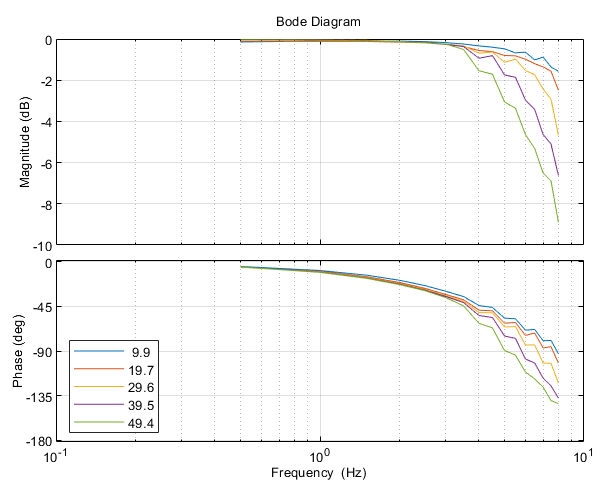
As you might expect, the amplitude and phase drops off quicker at higher amplitudes. This is likely due to velocity and/or torque saturation, or possibly other non-linear effects like friction within the servo.
Comparing the Savox and Corona at 20% (solid line) and 100% (dashed line) amplitude:
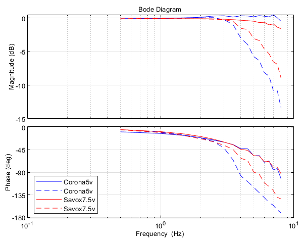
At low frequencies the performance is fairly similar, with a bandwidth of around 8 Hz (90 degree phase lag). At higher frequencies, the Savox has slightly better performance (4 vs 5 Hz bandwidth), probably due to its higher torque.
Step response #
The full range step response of the Savox is shown below. The full range is approx 120 degrees, which also allows the motor to reach peak velocity.
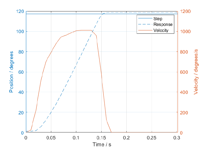
The peak speed is approximately 1000 degrees/sec, which corresponds to 0.06 seconds for 60 degrees, quite close to the spec.
Below is the 15 degree step response for the motor:
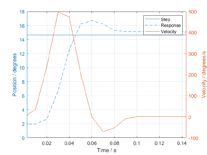
There is a small overshoot, that does not appear at higher step demands, a steady state error (caused by gear friction/backlash) and a 1 sample (10 ms) delay at the start due to the sampling size.
Overall, the performance is more impressive than I was expecting for these relatively inexpensive devices.
Conclusion #
These are some initial but hopefully interesting results from testing the servo motors. It was useful before they were used in the wing for flutter control to verify if it had any chance of working.
It would be interesting to know what the control architecture in the devices is like. Servos used to be all analog, I assume with a single op-amp acting as a proportional controller. The more modern servos (and the ones I tested) are digital, so have much more flexibility in terms of what they can do.
There are a number of other things I would like to test, and hopefully will in the future. These include:
- Repeating the tests with added inertia for a more realistic scenario
- Test the motors at difference voltages
- Produce a ‘spec sheet’ for each motor with a few performance parameters that define the behavior that can be used to compare. Things like small and large signal bandwidth, top speed, response time etc.
- Trying to estimate the motor constant, gear ratio and inertia.
- More measurements:
- Acceleration
- Current draw
- Stall torque
- Steady state error