UESB: Ultimate ESC Switcher Board

Table of Contents
Find all the source code and schematics here
Hardware #
Bidirectional control of a DC motor requires 4 transistors in an H-bridge configuration. This can be achieved simply and in minimal space by using an H-Bridge IC. The LV8548 is suitable as it is rated at 16v and 1A, supports PWM operation and is in a small but hand-solderable package (1mm pitch).
With in-built logic, each half-bridge can be switched to the positive supply or ground with a single logic input signal. This allows stand-by, forward, reverse and braking functions from 2 input signals. The motor drivers therefore require at least 12 I/O pins on the chosen micro-controller.
Another 2 pins are required to connect to the RC receiver channels, one for selecting the motor and another for setting the speed. The ATtiny416 has 17 available I/O pins, with interrupts for the RC inputs and plenty of RAM and processing power to do this relatively simple task. This leaves 3 input pins for changing settings in the firmware.
Components:
- LV8548 Dual H-Bridge IC (x3)
- ATiny416 MCU
- 0.1uF Capacitor (x2)
- Surface Mount DIP switch
Circuit #
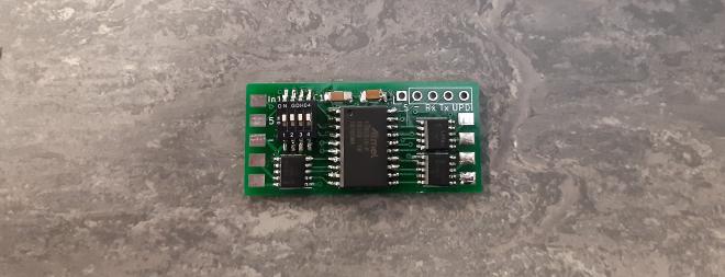
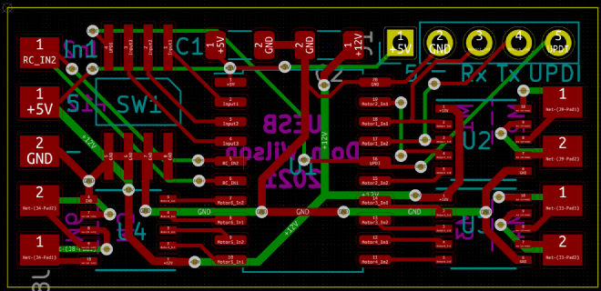
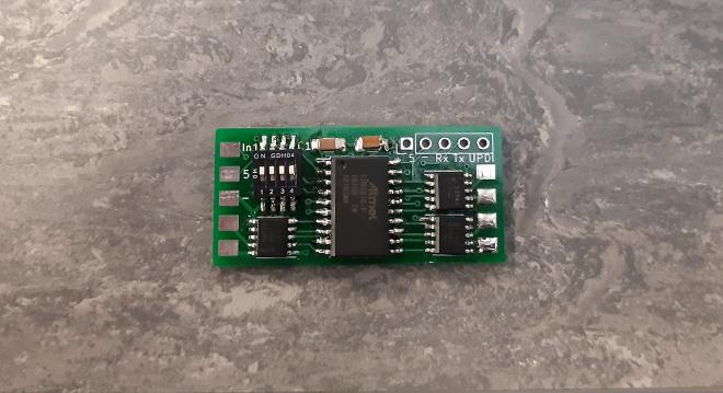
The circuit contains a nominal 12v rail for the motors and 5v for the micro-controller, both with decoupling capacitors and external connectors. A 5 pin breakout is included for programming as well as a DIP switch for settings.

PCB #
The PCB is designed with minimal footprint in order to fit into small models. Solder pads along each of the shorter edges are for the 12 motor connections, motor supply and ground, 5v supply and ground and the 2 RC inputs. A 2-layer board is easily sufficient for the routing.

The final cost for the components is ~£50 for 5 boards, including the PCBs from JLCPCB.

Firmware #
The firmware has 3 functions:
- Measure the RC input signals
- Determine which motor should be driven and at what speed
- Generate a PWM and logic signal for the motor active driver
PWM Signal Measurement #
A standard RC control signal is PWM with a high-time of between 1ms and 2ms and typically a period of 20ms. The most efficient and accurate method to measure this on a micro-controller is to use interrupts on the input pins.
The ATtiny416 supports pinchange interrupts on all IO pins, which are enabled for the 2 input pins as follows:
PORTA.PIN7CTRL = 0b00001001;
PORTB.PIN5CTRL = 0b00001001;
The pulse duration is measured using timer B, which is clocked from timer A at 1MHz.
TCB0.CTRLA = 0b00000101;
The state of each input pin is recorded in a struct which tracks the time of the rising edge, the current pulse width and whether the value has been updated since last check. The interrupt service routine (ISR) for each pin checks if the pinchange was rising or falling, and updates the struct accordingly. Since the pins are on different ports, it is not necessary to check which pin triggered the interrupt.
struct RCIN{
  uint16_t risetime;  // time of rising edge
  uint16_t pulse;     // length of pulse in (us)
  bool updated;       // true when pulse has been updated
};
volatile RCIN rcin[2];

ISR(PORTA_PORT_vect) {
  PORTA.INTFLAGS=255;               // clear the interrupt flags
  bool state = PORTA.IN & (1 << 7); // check if pin is high or low
  if (state){
    rcin[0].risetime = TCB0.CNT;    // if high, record timer b count
  } else {
    // if low, measure the pulse time
    rcin[0].pulse = TCB0.CNT-rcin[0].risetime;
    rcin[0].updated = true;
  }
}
Motor Switching #
There are 2 options for choosing which motor will be active, which are chosen based on the state of an input pin connected to the DIP switch:
- Continuous switching based on the pulse length of the RC signal
- Changing up/down with a switch on the transmitter
The continuous method uses the following thresholds, representing the pulse length in us. Below 1100us, motor 1 is selected. Between 1100 and 1300us motor 2 etc:
const uint16_t rcThresholds[] = {1100,1300,1500,1700,1900};
For discrete switching, two types of switches are common on RC transmitters; 2 position and 3 position. A 2 position switch will change between 1000 and 2000us, a 3 position between 1000, 1500 and 2000us. By tracking the transitions between each of these states, the firmware either increments or decrements the motor number.
The motor speed can be selected by a straight mapping from the pulse width centred around 1500us for forward/reverse, with a deadband at the middle and either end.
Motor Driver #
Timer A is used to generate the PWM signal on 1 pin of the active motor driver, whilst the other is held either high or low depending on the desired direction. It is configured with a prescaler of 16, which results in a clockspeed of 1MHz when the ATtiny internal clock is set to 16MHz. Two interrupts are used to generate the PWM signal, an overflow which occurs every 400us (2.5kHz) and a compare which is triggered when the timer count is equal to the value set in the compare register and can be anywhere between 0 and 400. The motor speed demand is mapped to the compare buffer TCA0.SINGLE.CMP0BUF in order to set the speed.
TCA0.SPLIT.CTRLA = 0; //disable TCA0 and set divider to 1
//set CMD to RESET to do a hard reset of TCA0 and enable for both halves.
TCA0.SPLIT.CTRLESET = TCA_SPLIT_CMD_RESET_gc | 0x03;
TCA0.SPLIT.CTRLD = 0;           //turn off split mode
TCA0.SINGLE.CTRLA = 0b1001;     //enable TCA and set prescale to 16 (1MHz)
TCA0.SINGLE.INTCTRL = 0b00010001;  // enable cmp0 and overflow interrupt
TCA0.SINGLE.PER = 400;          // timer will overflow every 400us (2.5kHz)
TCA0.SINGLE.CMP0BUF = 0;        // initial duty cycle is 0
On overflow, the active motor driver is set on, either forward or reverse depending on the current state. When the compare interrupt is triggered, the motor is set to idle state.
// compare interrupt for motor PWM generation
ISR(TCA0_CMP0_vect){
  // clear the interrupt flag of cmp0
  TCA0.SINGLE.INTFLAGS = (1 << 4);
  // turn the motor pin off
  set_motor_pin(state.motor,state.dir,0);
}

// timer overflow interrupt for motor PWM generation
ISR(TCA0_OVF_vect){
  // clear the interrupt flag of OVF
  TCA0.SINGLE.INTFLAGS = (1 << 0);
  // turn the motor pin on
  set_motor_pin(state.motor,state.dir,1);
}
Programming #
The ATtiny416 is programmed via UPDI, which requires a single pin on the MCU plus a power supply. The board breaks out these pins to a standard 2.54mm header along with 2 pins that can be used for serial debug if required (which disables motor 1).
Conclusion #
It works! Switching between motors seems to work flawlessly, and no issue driving small motors. It would be interesting to use the electronics hardware as a basis for further functionality by changing the firmware. Maybe to switch between profiles or drive groups of motors in a skid steer setup.