Arduino Uno R4 Rust - Part 1
Table of Contents
- Part 1 - Project config and UART
- Part 2 - RS232 + Better UART
Project Setup #
The UNO R4 contains an R7FA4M1AB3CFM#AA0 processor, or in short, an RA4M1. This is an ARM Cortex M4 that will run at up to 64 MHz, with 256 kB of flash and 32 kB SRAM. The instruction set is ARMv7-M Thumb and it includes hardware floating point, which will be orders of magnitude faster than doing floating point math on the Uno R3.
I have created the project using cortex-m-quickstart:
- cortex-m dependency, for core register definitions and peripheral access.
- cortex-m-rt dependency for initialisation.
- panic-halt dependency for halting the core on panic.
- Contains a
build.rsto specify linker arguments. - Template
memory.xfile (more below). - Template
.cargo/config.tomlto define a build target. - Has a minimal
main.rs
For a specific device, the target and memory configuration need changing.
The target triple is set in .cargo/config.toml as:
[build]
target = "thumbv7em-none-eabihf"
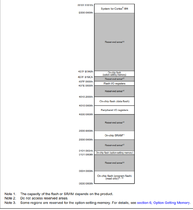
Checking the RA4M1 datasheet for the memory layout, flash starts at 0x0000_0000 at SRAM at 0x2000_0000:

The memory.x file in the project root is configured as so:
MEMORY
{
  /* NOTE 1 K = 1 KiBi = 1024 bytes */
  FLASH : ORIGIN = 0x00000000, LENGTH = 256K
  RAM : ORIGIN = 0x20000000, LENGTH = 32K
}
To get started, the only dependencies I am using are those in the quickstart template:
[dependencies]
cortex-m = { version = "0.7.7" }
cortex-m-rt = "0.7.5"
panic-halt = "1.0.0"
And main.rs looks like this:
#![no_std]
#![no_main]

use panic_halt as _;

use cortex_m::asm;
use cortex_m_rt::entry;

#[entry]
fn main() -> ! {
    asm::nop(); // To not have main optimize to abort in release mode, remove

    loop {}
}
Compiling #
The current program does nothing, but it does compile successfully. In order to flash to the Arduino, we need to extract the binary from the elf file in target. For this I am using cargo-binutils. I also quite like the just command runner, so in a justfile:
build:
    # Extract binary into hex for programmer
    cargo objcopy  -- -O ihex app.hex
Running just build compiles the program and extracts it into a hex file
Flashing #
Renesas have a cli programming tool rfp-cli available here. It supports the E2 programmers/debug tools and the MCU also has a built-in USB bootloader.
This is enabled by resetting the board with the boot pin shorted to ground, which can be used to flash the arduino bootloader if (when) things go wrong.
So with the boot pin shorted, device reset, it appears as a USB device:
lsusb
...
Bus 003 Device 008: ID 045b:0261 Hitachi, Ltd RA USB Boot
and is available for me at /dev/ttyACM0.
Then just run rfp-cli -device ra -port /dev/ttyACM0 -p app.hex right?
This worked, in that it flashed the program, but I also managed to brick the Arduino. Obviously the Arduino bootloader has been overwritten, but I also borked the ability to enter the built-in bootloader somehow.
Thankfully with an E2-lite debugger I was able to recover it by flashing the dfu_minima.hex bootloader and think about what I had done…
Not thinking hard enough #
I had no idea why that happened, so instead I persisted and tried to blink an LED. D13 is the UNO pin connected to an LED and looking at the datasheet on the RA4M1, this belongs to p111. Thats PORT 1, PIN 11.
The datasheet would suggest it is as simple as writing to the PDR register to set the pin as an output, and the PODR register to set the level. Thankfully, there is an RA-PAC crate available, which is added in Cargo.toml as so:
ra4m1 = { version = "0.2.1", git = "https://github.com/ra-rs/ra"}
Toggling the LED:
#[entry]
fn main() -> ! {
    // Get access to the peripherals
    let p = unsafe { ra4m1::Peripherals::steal() };
    // Set p111 as an output
    p.PORT1.pdr().write(|w| unsafe { w.bits(1 << 11) });
    loop {
        // Set output high
        p.PORT1.podr().write(|w| unsafe { w.bits(1 << 11) });
        // Set output low
        p.PORT1.podr().write(|w| unsafe { w.bits(0) });
    }
}
Flashing, disconnecting the boot pin from ground and then resetting, and the LED is on!. Looking at an oscilloscope trace, it is a square wave at 1.5kHz. WHY IS IT SO SLOW?!
I previously tried this with a slighty different program and it ran at 120kHz (more reasonable), but only ran for 8ms before rebooting…
Actually reading the datasheet #
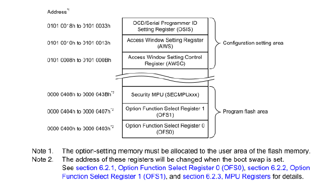
In section 6 of the RA4M1 datasheet:

Ah so there are some configuration settings in the flash memory where I dumped my program. Looking closer, these are related to the watchdog (explains the reset loop), the clock config (possibly explains the slow pin toggle but I am not sure) and the security config (might explain bricking access to built-in bootloader).
So what I should probably do is read the documentation throughly, configure the linker to set these to sensible values on boot and ensure the program is placed after the option registers in Flash…
… or I could just use the Arduino bootloader and not worry about it.
Note: The option and security MPU registers values can be seen in the Arduino bootloader binary, so maybe in future I’ll figure out what they do and use these (ihex format).
:10040000FFFFFFFFDFCEFFFFFCFFFF00FFFFFF004E
:10041000FCFFFF00FFFFFF00FCFFFF00FFFFFF00EE
:10042000FCFF0F20FFFF0F20FCFF7F40FFFF7F40FE
:10043000FCFF0D40FFFF0D40FFFFFFFFFFFFFFFF31
Using the Arduino bootloader #
As previosuly mentioned, the bootloader and how to flash it are here.
Looking at the Arduino core linker scripts, 0x4000 bytes (16kB) are reserved for the bootloader, so I shall do the same.
Thankfully, the cortex-m-quickstart memory.x file has a note about how to place the program start address in the case of configuration in flash:
/* You can use this symbol to customize the location of the .text section */
/* If omitted the .text section will be placed right after the .vector_table
   section */
/* This is required only on microcontrollers that store some configuration right
   after the vector table */
_stext = ORIGIN(FLASH) + 0x4000;
However, this would overwrite the bootloader vector table at the start of Flash, rendering it useless, so instead I shall just set the FLASH ORIGIN as 0x4000 and reduce the length:
MEMORY
{
  /* NOTE 1 K = 1 KiBi = 1024 bytes */
  FLASH : ORIGIN = 0x00004000, LENGTH = 240K
  RAM : ORIGIN = 0x20000000, LENGTH = 32K
}
I assume that the Arduino bootloader sets the Vector Table Offset Register to 0x4000, and this can indeed be verified:
// check VTOR register
  const VTOR_ADDRESS: *const u32 = 0xE000ED08 as *const u32;
  let value = unsafe { core::ptr::read_volatile(VTOR_ADDRESS) };
  if value != 0x4000 {
      p.PORT1.podr().write(|w| unsafe { w.bits(1 << 11) });
      loop {
          nop();
      }
  }
The cortex-m-rt crate has a feature-flag to set VTOR if you need it.
The other advantage of keeping the Arduino bootloader is that the binary can be flashed with arduino-cli, as well with the IDE as usual. It also configures the clock to 48 MHz and possibly some other non-default register values I am yet to discover.
It Works! #
Here is a trace of the output pin on a scope:

This is surprisingly slow for a loop consisting of 2 instructions.
Having a look at the generated assembly using cargo-asm, this is the partially unrolled led toggle loop:
.LBB4_1:
	strh r1, [r0]
	strh r2, [r0]
	strh r1, [r0]
	strh r2, [r0]
	strh r1, [r0]
	strh r2, [r0]
	strh r1, [r0]
	strh r2, [r0]
	b .LBB4_1
So this should be fast.
Turns out like all rust performance related issues, the answer is release mode. Building with --release, the output pin toggles at 6 MHz. I make that 4 clock cycles per write, which seems far more reasonable.
A couple things that still don’t make sense to me:
- The debug mode and release mode assembly are the same for the toggle loop, why the vast performance difference?
- The time between each level change is constant but there is a branch after 4 cycles, does the core manage to optimise that away?
Doing more interesting things #
Getting serial running seems like a good place to start as it will help get more insight into what’s going on (what’s a debugger?) and check if I can get interrupts working.
The peripheral used for UART is known as SCI and it can also do I2C, SPI amongst other things. The D0 and D1 pins on the UNO are used for UART and are connected to pins 301 and 302 in the MCU, which belong to SCI2.
The PAC comes in handy again, with the SCI configuration registers present at Peripherals.SCI2. Scrolling through chapter 28 of the datasheet, there is a Transmit Data Register (TDR) which is used to send data:
p.SCI2.tdr.write(|w| unsafe { w.bits(0x55) });
I have a scope probe on the tx pin. This does nothing yet.
Further on in the datasheet is the Serial Mode Register (SMR) which can be used to configure stop bits, parity, clock source etc. The defaults look reasonable for now.
Next useful looking register: Serial Control Register (SCR). This contains the te and re bits that actual enable transmissions and reception. No wonder nothing happened when writing to TDR.
p.SCI2.scr().write(|w| w.re()._1().te()._1());
p.SCI2.tdr.write(|w| unsafe { w.bits(0x55) });
Still nothing.
There is the Bit Rate Register (BRR). This will be useful later but default should do something.
Then the Serial Port Register (SPTR), nothing doing here.
Ahhh section 28.3 is all about UART, and 28.3.7 has an initialisation process. It boils down to configure all the registers as you need, configure the IO, then write SCR.TE and/or SCR.RE and possibly enable interrupts to get going.
I think the only bit missing for me at the moment is the IO:

Configuring IO #
Over to chapter 19 I/O Ports and there is a table that defines how each MCU function (SCI, SPI, I2C, CAN etc) can be mapped to the pins. The section of interest is here:

So the PSEL bits need to be 0b00100.
The PSEL bits are in the “Port mn Pin Function Select Register (PmnPFS/PmnPFS_HA/PmnPFS_BY)”
The PmnPFS registers are in the PAC at
Peripherals.PFS.
And this is where things got messy. To summarise a frustrating couple of hours, the UART config requires:
- Enabling the SCI2 peripheral in MSTPCRB register if it isnt already
- Resetting SMR to 0
- Configuring the rest of the SCI registers to achieve whatever UART setup is required
- Then to configure the IO, the following in order:
- Unlock the register that locks the PmnPFS registers
- Unlock the PmnPFS registers
- Clear the P302PFS register
- Set the TX pin as an output in P302PFS
- Enable transmission in the SCI2.SMR register (and Rx and interrupts as required)
- Set the P302PFS PSEL bits as above
- Set the P302PFS mode (PMR) bit (in a separate write to above).
- Optionally lock the PmnPFS registers
- Crying in relief that it finally works
The information required to get this to work is all in the datasheet, it just isn’t very forthcoming. The code can be found here.
With this setup, a byte can be transmitted by writing to the SCI2.TDR register
Interrupts #
SCI interrupts are available on the TDR register being ready for a new write, the end of transmission of a sequence of bytes and on reception of a byte.
On RA4M1 devices, the interrupts are controlled by the ICU, with the registers available at Peripherals.ICU. 32 interrupt vectors are available, and each of these can be mapped to any of the over 170 peripheral event sources by writing an event id to the IELSRx register.
The SCI interrupts for TDR available is mapped to the first interrupt as shown below:
unsafe {
    ra4m1::NVIC::unmask(ra4m1::Interrupt::IEL0);
};
unsafe { cortex_m::interrupt::enable() }
// Enable interrupt for SCI2_TXI
p.ICU.ielsr[0].write(|w| unsafe { w.iels().bits(0x0A4) });
Then the interrupt routine to place the next byte in the TDR register:
#[interrupt]
unsafe fn IEL0() {
    // Interrupt for SCI2_TXI
    static mut count: u8 = 0;
    *count = count.wrapping_add(1);
    unsafe {
        ra4m1::Peripherals::steal()
            .PORT1
            .podr()
            .write(|w| w.bits(0))
    };
    // Clear the interrupt flag
    ra4m1::Peripherals::steal().ICU.ielsr[0].modify(|_, w| w.ir()._0());
    // Place data in SCI2 transmit data register
    unsafe {
        ra4m1::Peripherals::steal()
            .SCI2
            .tdr
            .write(|w| w.bits(*count))
    };
}
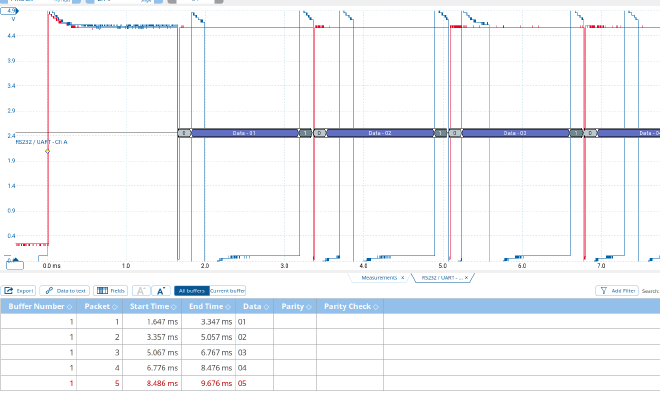
It also pulls the led line low, as shown by the red trace, with the UART output in blue:

The Transmit end interrupt doesn’t do anything useful for now as the transmission never ends.
The scope does a decent job decoding this, it even automatically figured a baud rate of 5.8k:

Baud rate #
The BRR register is the main method of configuring the baud rate, with an 8 bit value that defaults to 255. Using the equations in the datasheet, based on the 48 MHz clock, a value of 155 yields 9600 baud. This will do for now.
Making it usable #
All I really want to do is send and receive strings to a serial console for debugging. For sending, this will be something like call a serial_print(str: &str) function that:
- Puts the data into a circular buffer
- Enables interrupts that pull a byte at a time from that buffer
- If buffer is full, wait until more data can be placed
- return when all the data is in the buffer
Optionally a flush function would be handy as well that could wait until the buffer is empty i.e all data sent.
For this I have defined a Tx struct that exists inside a static Mutex. Access to it is only available inside a critical section with interrupts disabled. Tx contains a buffer from the circular_buffer crate:
static TX: Mutex<RefCell<Tx>> = Mutex::new(RefCell::new(Tx::new()));

struct Tx {
    buffer: circular_buffer::CircularBuffer<64, u8>,
}

impl Tx {
    const fn new() -> Self {
        Tx {
            buffer: circular_buffer::CircularBuffer::new(),
        }
    }

    // Can be called in the TEI interrupt handler if more data is available
    // in the buffer or when new data is added to the buffer
    fn start_transmit(&mut self) {
        let p = unsafe { ra4m1::Peripherals::steal() };
        p.SCI2.scr().modify(|r, w| {
            if r.tie().bit_is_set() || r.teie().bit_is_set() {
                // do nothing, transmission is already in progress
                w
            } else if !self.buffer.is_empty() {
                w.te()
                    ._1() // Enable transmission
                    .tie()
                    ._1() // Enable transmit interrupt
                    .teie()
                    ._0() // Disable transmit end interrupt
            } else {
                w
            }
        });
    }
}

pub fn serial_print(str: &str) {
    // Convert string to bytes
    let bytes = str.as_bytes();
    // track index of bytes
    let mut index = 0;

    loop {
        // Loop until all bytes are pushed to the buffer
        let mut done = true;
        let p = unsafe { ra4m1::Peripherals::steal() };
        // Get access to buffer

        critical_section::with(|cs| {
            let mut tx = TX.borrow(cs).borrow_mut();
            // Loop through remaining bytes

            for (i, b) in bytes[index..].iter().enumerate() {
                // try push byte to buffer
                if tx.buffer.try_push_back(*b).is_err() {
                    // Buffer is full, exit loop to release critical section
                    // and allow the interrupt to add more data to uart
                    index += i;
                    done = false;
                    break;
                }
            }
            // Ensure that the transmit starts
            tx.start_transmit();
        });
        if done {
            // All bytes were pushed to the buffer, exit loop
            break;
        } else {
            // Not all bytes were pushed, wait for the interrupt to handle the buffer
            cortex_m::asm::wfi();
        }
    }
}
The serial_print function returns when all the bytes of str are pushed to the buffer and the transmission is in progress.
start_transmit() is a method on Tx so that interrupts are disabled when manipulating the SCR register. I am sure there is a way of doing this lock-free, but it will do for now.
There are now 2 interrupt handlers, one for when the peripheral is ready to send the next byte and one for when all bytes are sent. These look like:
#[interrupt]
unsafe fn IEL0() {
    // Interrupt for SCI2_TXI

    // Clear the interrupt flag
    unsafe { ra4m1::Peripherals::steal().ICU.ielsr[0].modify(|_, w| w.ir()._0()) };

    // Lock the buffer to get access to it
    critical_section::with(|cs| {
        let mut tx = TX.borrow(cs).borrow_mut();
        // Pop a byte from the buffer
        if let Some(value) = tx.buffer.pop_front() {
            // Write the value to the transmit data register
            unsafe {
                ra4m1::Peripherals::steal()
                    .SCI2
                    .tdr
                    .write(|w| w.bits(value))
            };
            // check if the buffer is empty
            if tx.buffer.is_empty() {
                // Disable the transmit interrupt and enable the transmit end interrupt
                unsafe {
                    ra4m1::Peripherals::steal()
                        .SCI2
                        .scr()
                        .modify(|_, w| w.tie()._0().teie()._1())
                };
            }
        } else {
            // No more data in the buffer, disable the transmit interrupt
            unsafe {
                ra4m1::Peripherals::steal()
                    .SCI2
                    .scr()
                    .modify(|_, w| w.tie()._0().teie()._0());
            }
        }
    });
}

#[interrupt]
fn IEL1() {
    // This is the interrupt for SCI2_TEI
    // Triggers when the last byte has been transmitted
    // Clear the interrupt flag
    unsafe {
        ra4m1::Peripherals::steal().ICU.ielsr[1].modify(|_, w| w.ir()._0());
    }

    // Disable transmission and interrupts
    unsafe {
        ra4m1::Peripherals::steal()
            .SCI2
            .scr()
            .modify(|_, w| w.teie()._0().tie()._0().te()._0());
    }
    // Try start again if needed
    critical_section::with(|cs| {
        let mut tx = TX.borrow(cs).borrow_mut();
        // Start transmission if there is more data in the buffer
        tx.start_transmit();
    });
}
The process for sending data is:
- Put data in buffer
- Enable
SCR.TE(enable transmit) andSCR.TIE(enable transmit interrupt) bits - Each
SCI2_TXIcall, get a byte from buffer and place inTDRregister.- If it is the final byte, disable
SCR.TIEand enableSCR.TEIE(interrupt end)
- If it is the final byte, disable
- When the final byte has been sent,
SCI2_TEIfires andSCR.TE,SCR.TIEandSCR.TEIEare all disabled. Then check if any other data has been placed in buffer (i.e another call toserial_printas the final byte was sent), and restarts transmission if there is.
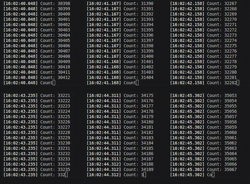
And it works! I changed the BRR register to 15 for 115200 baud. This is the serial monitor connected to the TX pin:

Receiving #
I won’t go into too much detail here, but receiving is basically the opposite. An interrupt fires, a byte is fetched from a register, placed in a circular buffer ready for a periodic call to serial_read to pull data from the buffer.
It is slightly more complicated in that receiving errors can occur, for which an error interrupt handler can be registered to check and clear error flags.
Improvements #
The commit containing UART tx and rx as described is here. It is very much WIP and will likely be changed.
One of the aims of this is to start to put together a HAL like those in stm32-rs or embassy. A UART implementation would be a good start to that.
Lock free buffers #
Currently accessing buffers requires a critical section and therefore disabling interrupts. The accesses are very short so this isn’t a massive deal, but I would like to switch to something like embassy’s Atomic RingBuffer.
Embedded-IO traits #
Implementing the embedded-io Read and Write traits would make this far more useful, and probably force me to make the design a bit more sensible. This would require a receiver and sender struct that would be owned by the user on which the traits would be implemented.
Ownership #
Most rust HALs take ownership of the registers and sometimes pins to prevent them being messed with (at least outside of unsafe). That’s easy enough for the SCI register, but I need to look into how splitting ports into pins is achieved in other HALs.
Implement for any SCI peripheral #
The RA4M1 has 5 SCI peripherals, I think 3 are broken out onto pins on the UNO R4. The implementation would basically be the same for each and likely for other devices in the Renesas RA family.
This post is long enough, so these will come next time.
Conclusion #
Rust on an UNO R4 is possible and quite easy mainly thanks to the Cortex-M team in the Embedded devices Working Group. With its physical and electrical compatibility with the UNO R3, I think it could be a useful device for some projects, and I am currently using it for its CAN peripheral.
More on getting CAN working and a rust CANOpen library I am developing coming soon…