Active Wing Flutter Control
Table of Contents
This is a project devised by Dr Sam Bull to educate and inspire school students interested in STEM subjects and to demonstrate the capabilities of The Mini Wind Tunnel Project.
What is aerodynamic flutter? #
I am no aerodynamicist, but here we go. Flutter is when the aerodynamic forces acting on a wing create positive feedback, extracting energy from the airflow and driving the wing into oscillation. If not dealt with, the oscillations could grow, and the wing will shake itself apart. This is bad.
Care is taken during the aircraft design so that this doesn’t happen in the airspeed range in which they operate. However, if active flutter prevention is available, this would expand the limits of wing designs, such as allowing more slender and efficient wings.
How to demonstrate flutter #
Simple. Mount a wing in a wind tunnel and ramp up the wind speed until the oscillations occur.
However, getting the wing to flutter requires the correct inertial, stiffness and aerodynamic properties of the wing, and for it to occur within the speed capabilities of the tunnel. And the wing needs to fit in the tunnel.
An aircraft wing is a cantilever beam, with a mass, and a stiffness depending on the geometry and materials. Therefore instead of placing a model of a full length wing in a wind-tunnel, a section can be used, mounted on springs to represent the wing stiffness. This has the added benefit of independently setting the inertial and stiffness properties for fine tuning.
The wing was designed and springs chosen based on aeroelastic theory and after hours of tweaking the mass distribution and spring placement, aerodynamic instability was finally achieved:
It was not simple.
How to stop flutter #
Now to try and stop the flutter that occurs above a certain wind speed. The wing is driven by the aerodynamic forces acting on it, so to control flutter requires manipulating these forces. This is the job of a flap that is built into the wing. The flap can rotate up or down, causing the wing to pitch upwards or downwards respectively. Combining this flap with sensors to measure the wing motion and a microcontroller, active flutter control may be possible.

Wing design #
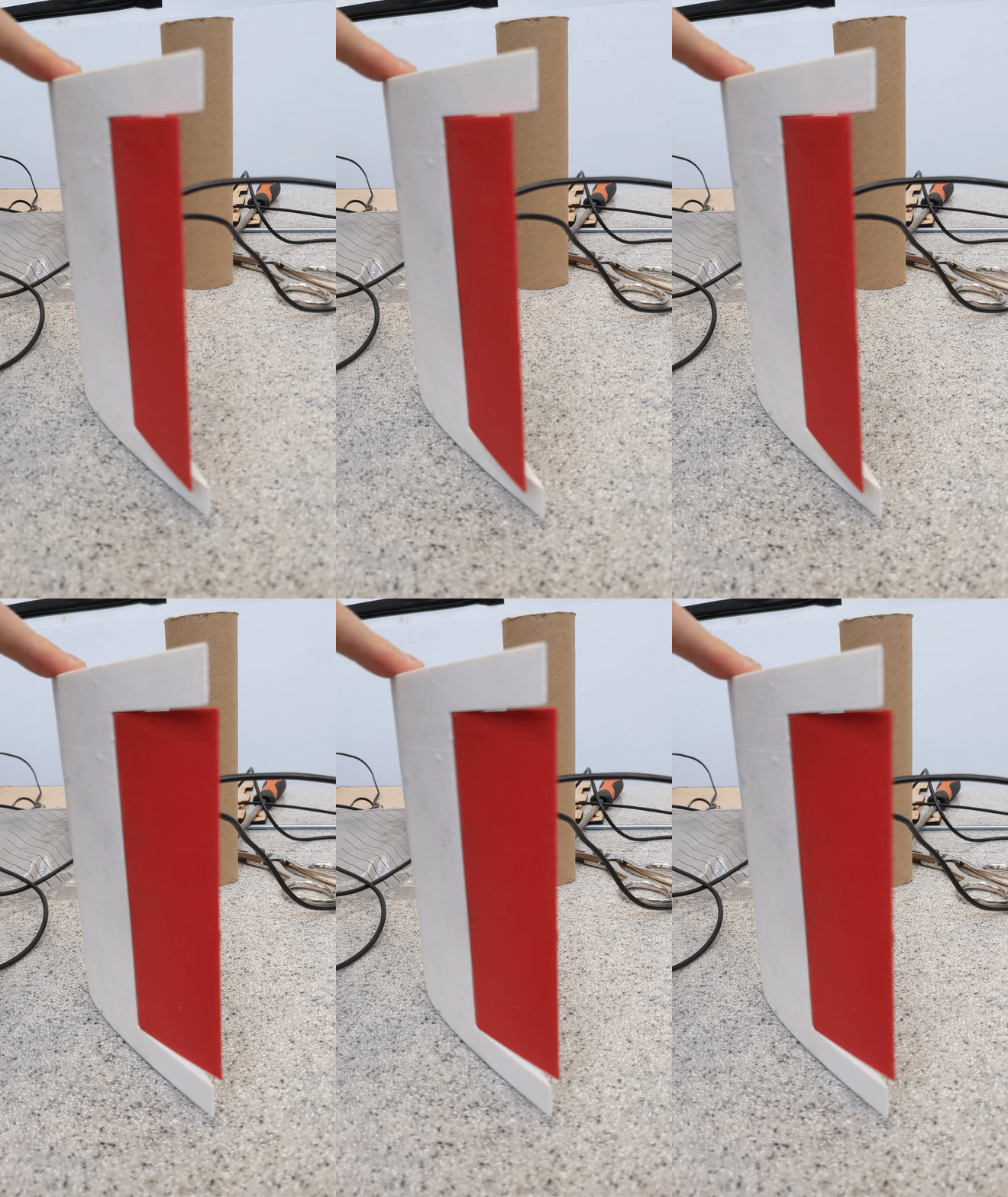
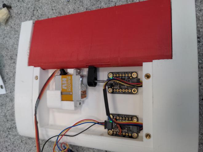
The wing is a 3D printed NACA aerofoil, with a relatively large cutout for the flap. The large surface area of the flap allows for greater control authority to affect the flow. The flap is driven by a high performance, low profile servo motor via a toothed connector. The motion of the wing is measured by 2 Inertial Measurement Units (IMUs), which can measure the angular velocity and linear accelerations in the plane in which the wing can move.

Electronics #
Parts:
- MPU6050 IMU (x2)
- Savox SV1232MG Micro digital high voltage servo motor
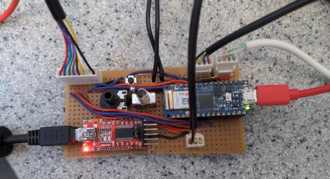
- Arduino Nano IOT 33 microcontroller board
- USB to UART converter
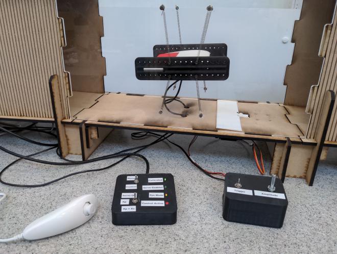
- Nintendo Wii Nunchuck
- Misc connectors, wires and buttons
Due to space constraints inside the wing, the microcontroller board is placed outside the tunnel, with wires connecting the power and communication signals to the motor and IMUs.

The microcontroller also connects to a control box with a couple of switches and indicator LEDs, which allows for switching between different operating modes, including a manual mode where the user can control the wing flap using a joystick.

The IMUs and joystick (Wii Nunchuck) communicate via I2C and are all connected to the same bus. The servomotor uses the standard 1-2ms PWM signal to control its position.
Software #
The software is written in C++, using the platformIO extension in VS Code for compiling and uploading to the Arduino. 2 serial interfaces are used, one for debug/error messages and sending commands, and another for streaming data for visualisation on a computer.
After initialisation of the serial interfaces, IMUs, controller etc, the microcontroller runs a timer interrupt driven control loop at 100 Hz. Each iteration of the loop does the following:
- Fetch the IMU gyro and acceleration readings
- Filter the gyro and acceleration readings
- Fetch the nunchuck joystick position
- Sample the digital inputs from the control box
- Calculate the motor control signal using the chosen control method
- Set the servo motor demand
- Output readings and info to the data streaming serial/UART
IMU Filtering #
The wing is constrained in a plane, allowing it to pitch, and translate vertically and horizontally. From the video above, the main oscillations are in the pitch and vertical directions. Controlling this motion therefore requires measurements of the pitch and vertical motion.
The IMUs each contain a 3-axis gyroscope and 3-axis accelerometer. Therefore direct measurement of the only the pitch velocity and linear acceleration are available.
Estimating pitch angle #
One method to calculate the pitch angle would be to integrate the angular velocity over time, however this would lead to long term drift. Another would be to calculate the angle of the gravity vector based on the x and z acceleration measurements, but this is only accurate when the wing is not accelerating. Thankfully there are methods of combining the 2 methods which are more accurate than each individually, such as the Madgwick Filter. This is probably overkill as it does full 3D orientation, but it works well. This implementation from xioTechnologies was used.
Estimating vertical velocity #
Velocity can be calculated by integrating the z-axis acceleration, however this comes with a few issues:
- Accelerometers measure 1g from gravity so this needs to be subtracted
- There will an error as the wing pitches from horizontal
- It will drift over time due to errors
Problem 1 is solved by the Fusion library above, as linear accelerations with the gravity vector removed are made available.
Problem 2 is solved by calculating the z and x axis velocities and resolving to the vertical direction using the estimated pitch angle.
Problem 3 is a solved by using a low-pass filter as an integrator, where only velocities above the cutoff frequency of 1 Hz are measured. This is explained below.
Velocity filter #
Below is a block diagram for an integrator:
This will drift over time due to measurement errors and noise. Adding feedback can reject the low frequencies and prevent drift. The block diagram looks like this:
The transfer function is a 1st order with a cutoff frequency of K (rad/s):
$$ \frac{Acc}{Vel} = \frac{1}{S + K} $$
This is ok because lower frequencies aren’t of interest for the controller, which is only concerned with flutter. However it will still leave a bias since the accelerometers aren’t perfectly zeroed, and any offset in acceleration measurement will make it through.
A high pass filter with a cutoff of 1 Hz is placed in series with the low pass filter to remove any steady state bias in the velocity estimation:
The transfer function for this 2nd-order filter is:
$$ \frac{Acc}{Vel} = \frac{S}{S^2 + 2KS + K^2} $$
The denominator is critically damped, with the frequency tuned by the parameter K. This is set to 1Hz (6.28 rad/s) as a tradeoff between low frequency rejection and a sufficiently accurate higher frequency signal.
The frequency response of the 3 integrating filters is shown below:
Above 1Hz, both the 1st-order and 2nd-order filters converge upon the ideal integrator. The low frequency rejection of the 2nd-order filter is clearly the best.
Control Tuning #
Pitch angle, pitch velocity and linear velocity are available for feedback. The velocities are likely to the most important as they add damping to the system, and flutter is caused by negative damping.
Various combinations of these were trialed, with pitch angle and linear velocity proving to be the most effective together. More work is needed theoretically and experimentally to explore this.
The block diagram below shows the control architecture that was used in the final setup:
The accelerations measured by the IMU, \(\ddot{x}\) and \(\ddot{z}\), are resolved using the pitch angle \(\alpha\), and then filtered to get the vertical velocity \(v_z\). Both \(v_z\) and \(\alpha\) are used with their respective gains \(K_v\) and \(K_\alpha\) to generate the control signal to command the motor position.
Results #
The following are a selection of videos showing the performance of the wing active flutter control.
Active flutter control #
Comparing the stability of the wing with the control on and off
Slow motion of the flap in action #
Initially the controller is disabled, allowing the oscillations to grow. The controller is enabled roughly when the slow motion starts, and is able to recover and stop the oscillations.
Disturbance generator #
The disturbance generator periodically lifts a flap in the floor of the tunnel, generating a gust that could potentially caused the wing to go unstable. The controller is able to prevent this
With Joystick #
Trying to stabilise the wing using the joystick… and then holding the button for cheat mode