Distributed Pressure Sensors for Wind Tunnel Testing

Table of Contents
Project description #
The aim of this project was to sample dynamic pressure data from the surface of a wing placed in a wind tunnel and feed this data back to a data acquisition system for logging and potentially real-time control or Hardware-in-the-loop testing in the future.
Sensors #
Pressure taps are placed around the surface of the wing, which are small steel tubes that are connected to high performance pressure sensors on the inside of the wing via flexible hosing.
The sensors in question are part of the HoneyWell HSC series, which come in a wide array of pressure ranges, interfaces, voltages, footprints and barb layout. I am using the 3.3V, differential, SMT mounted, I2C, RR version shown below.

The sensors can sample at up to 2 kHz, but for this project 1 kHz is sufficient, with the data being sent back to a Speedgoat running Simulink real-time, ideally with less than 1 sample, i.e 1 ms, latency.
Architecture #
The I2C interface poses a problem as each device on a bus requires a unique address, but these sensors are only available with 6 unique addresses, and we need around 40 sensors. Moreover, its only possible to purchase in bulk, which means all sensors have the same address anyway.
The way around this is to use an I2C switch, which can route the master I2C bus to any of 8 downstream buses. The switches themselves have up to 8 addresses, so all sensors could fit on a single bus, however it would greatly reduce the sample rate.
Each read to a sensor requires exchanging 3 bytes: 1 for the address, 2 to read the 16 bit value. With the I2C switch there is 1 byte address + 1 byte selection overhead, that is 5 bytes per sample. For a 400 kHz bus, this amounts to approximately 125 us per sample. Leaving some overhead, 6 sensors per bus is within the 1 ms target for a 1 kHz sample rate.
For cost and simplicity, the design is based on an STM32 Nucleo F7 board, which includes 4 I2C buses and an ethernet port. 2 Nucleos x 4 buses x 6 sensors = 48 sensors, more than enough for the project. The data can be read from each of the 24 sensors per board and sent over UDP back to the Speedgoat.
PCB Design #
Two PCBs are required for the project. One that breaks out the I2C buses and 3.3V/Gnd on the Nucleo to connectors that go to the second PCBs: sensor boards containing the I2C switches and pressure sensors. This is to give flexibility in the layout within the wing, and ensures the sensors are as close to the taps as possible, which is important for the dynamic performance of the measurements.
The mainboard also:
- Connects to a 24 V power supply, stepping it down to 5V to supply the Nucleo.
- Connects to an output pin on the Speedgoat to trigger sampling
- Has configuration switches to set device ID (so each Nucleo can use the same firmware, automatically configuring MAC/IP address).
- Has configuration switches for setting sample rates and sampling modes.
Below is one of the mainboards. The left ribbon connectors each contain 2 I2C buses + power, the right each have 1 bus + power, allowing the Nucleo to connect to a combination of single sided and double sided sensor boards.

Sensor board #
The sensor boards are double sided, each side containing an I2C switch, slots for up to 6 sensors, decoupling capacitors and I2C pullup resistors for each bus.
Below is a sensor board with a single sensor. The 6 pin ribbon cable contains 1 or 2 I2C buses from the Nucleo + 3.3V and Gnd, depending on whether it used as single or double sided.

Complete hardware #
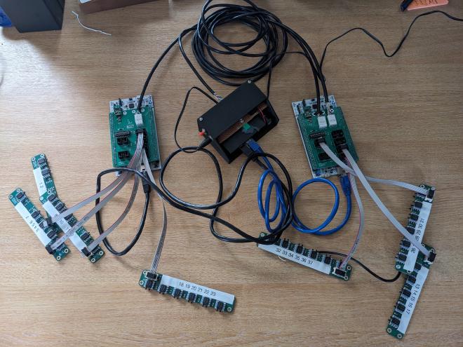
The complete assembled hardware includes a module that lives outside the wing containing a switch and power supply routing to the board, with a reset button to reset the system if required.
Each sensor is numbered according to its position around the surface of the wing, which is also configured in the firwmare.

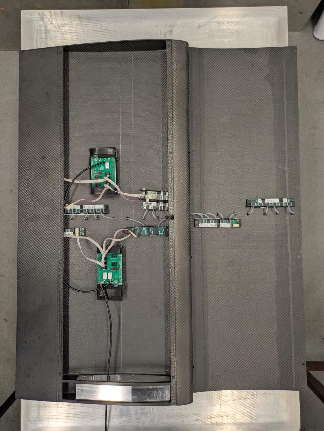
Installed inside the wing:

Firmware #
The firmware is relatively simple and entirely interrupt driven. In the synchronous mode, each device waits for a changing edge on a GPIO pin, delivered by the Speedgoat. This triggers a sequence of up to 6 sample cycles on each of the 4 I2C buses in parallel. This is configured by a data-structure that informs the device about the ID (as in the image above) of each sensor on each bus, and whether it is present or not. It is important to minimise the time between each byte on the I2C bus, hence being interrupt driven.
Once every sensor has been sampled, the data is packed into UDP frame and sent over the network, along with some timing, error and sequence count information.
CLI Tool #
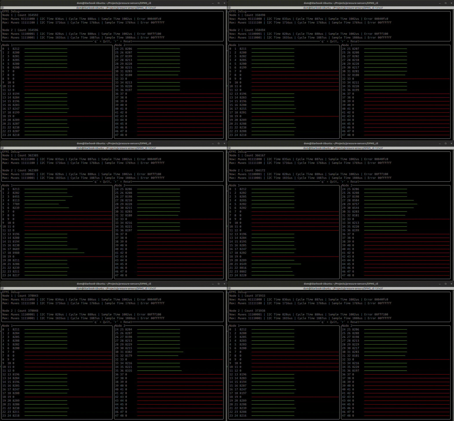
During development, I did not have access to a Speedgoat for testing, so I created a CLI tool to connect to the system and display the data. This tracked how long each cycle took, any errors that occurred and displayed the pressure sensor data in real-time. It was built with Rust and the ratatui library.
The GIF below shows it in action, although without all the sensors present. The motion of the green bars is the sensor response to me tapping on them.

I also tried sampling sensors at above 1 kHz and added a feature in the CLI to show if the read fails, flashing in blue in the image below. In theory this should work up to 2 kHz, but this batch of sensors appeared to have an issue.

Simulink #
The Simulink library for receiving pressure sensor data had to:
- Send a 500 Hz square wave output for a 1 kHz sample time.
- Listen to UDP packets
- Extract and combine the pressure sensor data from each source into a 48 wide array
- Rearrange and reduce the array into 40 sensors, ordered by their ID as labelled on the PCBs.
It also warned the user of missing data, which could occur if a UDP packet did not reach the Speedgoat in time.
Conclusion #
The system was successfully deployed and is currently in use for a research project investigating unsteady aerodynamics. The aim of 1 kHz sampling time was achieved, with the I2C sampling times consistently around 850 us for the up to 48 sensors that can be configured on the system. By using the dev boards, low-cost PCBs assembled in-house and simple firmware, the final cost was affordable for a University research project.
One issue with the sequential sampling approach is that each sensor on a bus is sampled at slightly different times, i.e ~125 us between each. This is adjusted for in post-processing of the data, so isn’t a big issue. For a potential future, higher performance implementation, I may look into either distributing more microcontrollers throughout the system or bit-banging many I2C or SPI buses for better parallel sampling.